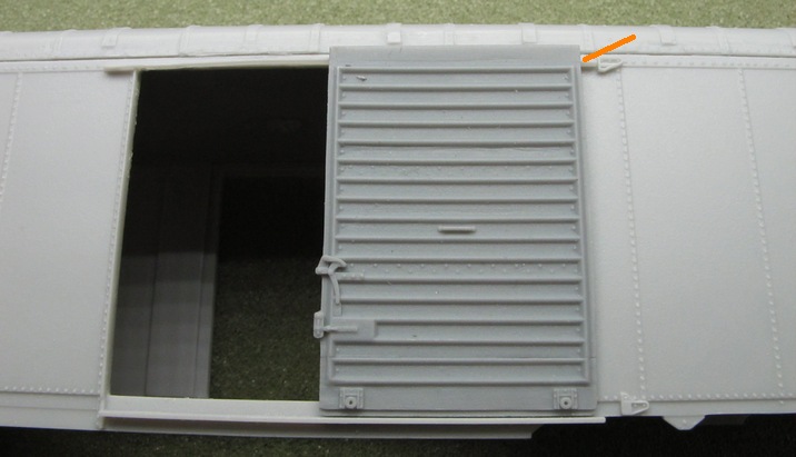
The instructions state that the door's rollers should be in the same vertical plane as the bottom door track (see orange marker). On my model it appeared that they were, so I didn't need to make any adjustments to the door track.
Positioning the door on the model clearly showed how much material needed to be removed from the door. I used a flat file clamped to a flat surface to file the top of the door down, testing the fit every few strokes.
After gluing the doors to the body, I went back and added reinforcements on the inside. Since I had removed the material in the door opening before I read that that material was there to hold the door in place if you are not modeling an open door model, I had to go back and add my own version. There just isn't much glue surface between the door and the body and I didn't want to risk it falling off sometime down the line. Just a few scrap pieces of styrene did the trick.
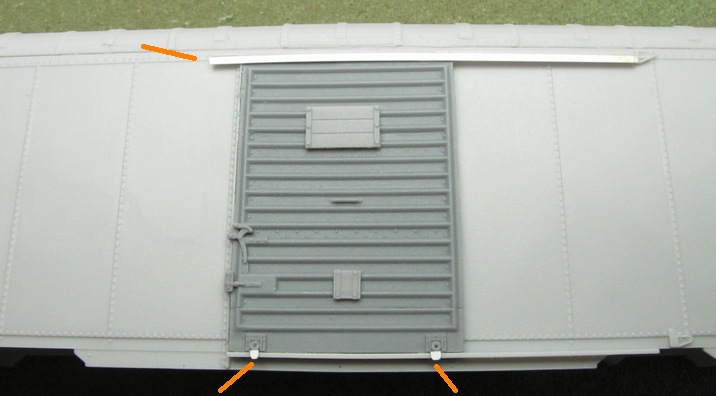
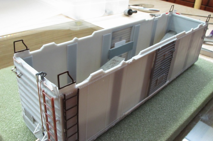
This photo shows several updates. First, I used a piece of the provided strip styrene to make the top door track. I just glued it on top of the door and underneath the body casting's lip. That seemed easier than trying to get it to lay on top of the casting's lip as the instructions seemed to suggest. That may be more correct, but it is a lot more difficult to get right, and since the door doesn't open, there is no need for it, I think. I also cut two tiny pieces of styrene for the door guides at the bottom of the door. I checked the prototype photos and it seemed like they had a chamfered corner at the bottom corners, so I modeled that by filing the corners down. I just glued them on top of the bottom track under the door wheels. Finally, the two tack boards were installed. Note that the small one at the bottom is rotated 90 degrees from the way the large one is oriented. That way the bolt heads line up with the ribs of the door.
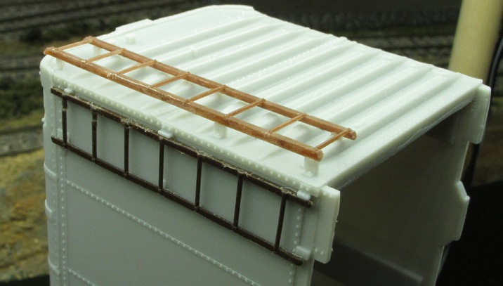
The ladders were actually quite a bit of work to get right. The longer one at the top had to have its step rung cut off from it. All ends of the ladders needed to be filed down a bit to give them a rounded edge. The hard part was the installation. All pins need to be cut off and filed smooth on their backs. The ladders don't quite match up with the casting spots on the body, especially for the one on the side wall. Also note to be careful in removing the ladder from the sprue, because no matter how you try to cut it free, one or more of the rungs will break.
The instructions on how to detail the "B" (brake) end of the car are fantastic, so I will only highlight items I had problems with. In this next photo you can see several parts already installed. I was confused as to where the hole in the bottom of the body casting was to be drilled, but it should be directly below the brake house (the large dark gray part). See the pencil mark. Since I shortened my underbody casting rather than modified the body casting (as the instructions suggest), I didn't need to make any adjustments to the underbody to accommodate this next part.
After drilling the hole, the brake rod bell crank part was installed. I put some weights on the body to hold it straight while I was working with this part.
Of course, next up is the connection of the brake housing part with that bell crank. Here's my overall set-up to make this happen.
I glued a clevis to each end of the brass wire. One was glued to the bell crank (out of the photo), and the other was glued to a short piece of chain. The other end of the chain was glued to the under side of the brake housing. The end of the file is used to hold the assembly at the correct clearance from the body while the glue set.
I wasn't clear about what part of the brake platform that needed to be cut off, so needless to say, I did the first one incorrectly. It is a good thing there is an extra one in the kit. This photo shows how it needs to be cut to get it to fit properly.
This photo shows the brake platform installed as well as the end tack board. Attaching the tiny parts that hold the bottom grab irons was an exercise in patience! I found it easier to drill the hole just a bit larger before installing the part on the body. Fingernails come in handy for holding those tiny parts. To install them, I placed a small drop of superglue in the flat space between the rivets along the bottom edge of the body. Then, with a tiny pair of tweezers, carefully place the part on the glue. You'll have a second or two to get the part in the correct position. You have to hold the part steady until the glue grabs, because most of the body weight of the tiny part hangs off of the body, so there is nothing holding it up until the glue sets.
I hate to be the bearer of bad news, but this kit gets more challenging as you go on! These little A handhold brackets are a genuine pain. For the "B" end of the car, I first formed the metal bracket stands, and then glued them to the car body (use the holes on the car body as general guide, but there is just no way you'll get the bracket stands' holes to line up with them!). I then installed and glued two bolts into the metal cross piece, as shown in the middle of the photo.
For the "A" end of the car, I decided to pre-assemble the whole handhold before installing it on the body. Neither method was any easier. They both require a healthy dose of patience.
Once the brackets were glued to the body, I drilled the holes out and as far as possible into the body. The deeper, the better. That way your bolts can have a long shank, which makes them easier to insert into the hole. A tiny drop of superglue holds the bolt and the bracket together. It is not perfect, but looks OK, as long as you don't look at it as close as I am with the camera. The "A" end of the car is identical to the "B" end, minus the brake gear assembly, of course.
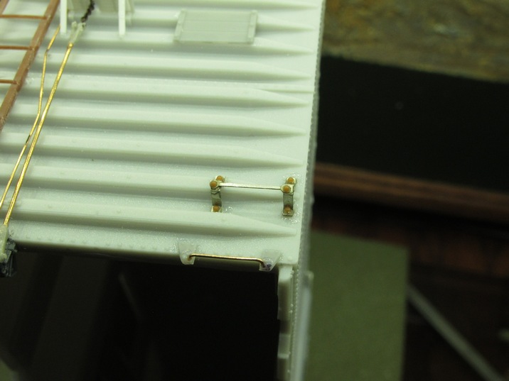
Next up is the roof. Installing the walkway and its corner platforms is relatively straight-forward. I didn't find a way to mount the corner platforms, so I just leaned them up against the walkway and applied superglue to the seam. I then drilled #76 holes for the brass wire grab irons. The pre-formed holes didn't seem to line up with the corner hole correctly, so the corner brass wire is some distance away from the grab iron itself. The instructions say to use a piece of strip styrene to glue the walkway end support brackets. However, I prefer to form mine out of scale 1"x2.5" brass stock. Also, there is a horizontal bar between the brackets, if you look at the prototype photos. I found it easiest to form both of these brackets and glue them to their horizontal bar away from the model.
It was then much easier to glue the assembly to the bottom of the walkway and to the end panel, rather than doing each bracket separately.
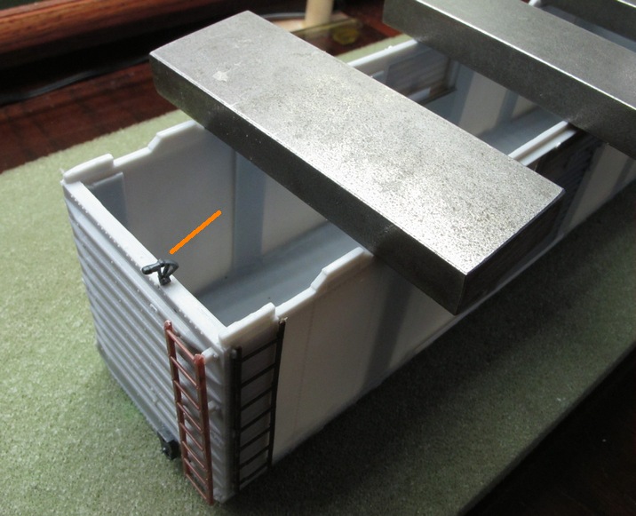
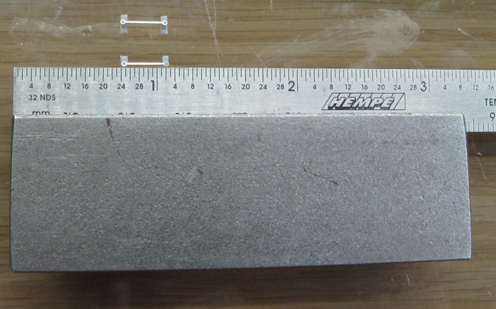
The car's sides are fairly simple. The first thing to do is to assemble and glue to grab irons. These are made from two styrene brackets and a metal bar that goes between them. The brackets have an opening in their top. The orientation of the opening needs to be such that it is facing the other bracket (i.e. it is hidden under the metal bar). I found the holes of the metal bars to be just the right size for the dimple on the top of the styrene brackets. I found it easier to assemble the whole grab iron "off line". I put a small ruler on top of the brackets, with a metal weight on top of that, to hold the brackets in place and at the correct distance from each other. I could then carefully place the metal bar on top of them, and then apply a small drop of superglue to the dimple. This produced better results than attaching the brackets to the car first.
Again using some weights to hold down the assembly, I could then apply some superglue to attach the brackets to the car body. I used the holes in the body as placement guidelines only, and made sure the brackets covered them.
The other item that needs to be installed on the sides are the corner steps. There are two options provided in the kit. The metal ones are more to scale, but are extremely delicate. I tried to form one, and it broke in several places before I even had it shaped correctly. I figured my odds for success were going to be slim (you only get one extra one), so I switched to using the cast plastic ones instead (may prove to be sturdier to handle being transported to and from local train shows).


