For the trucks and wheels I have decided to use the M.T.H. AAR Type Y ones. These roll very freely, and work well. The wheels are scale and look nice. I got mine from Sidetracks. Note that these are also available with hi-rail wheels, for those who prefer those.

To install these, I first used a tap for the 2-56 screw I intend to use here. The hole was already carefully drilled when I assembled the basic frame (see "Construction: Frame"). Back then I had made this part of the truck bolster/frame out of some thick blocks of styrene, so that there would be plenty of thread for the screw. I took my time with the tap, because if this goes wrong, fixing this is a real pain. I put one thin washer in between the truck and the car, and slowly inserted and tightened the screw. I backed-off the screw by about 1/8th of a turn to give the truck freedom to swivel, but not be loose. In this photo I show the maximum swing that the trucks have. More than enough of a true scale layout.

Next, I wanted to convince myself that the trucks and the body are in perfect alignment with each other. I used my Coupler Height Gauge board to do this. With the car correctly on the jig, I use a metal square to see if the body sits straight on the trucks. It looks like it does.

I didn't bother putting the wheels on the car until near the end, because otherwise they would just get in the way of construction. However, I now want to work on installing the couplers, so their position is dependent on how high the car body sits. While the car was on my jig, I rolled it to the end where I have a block of wood. The top of the block of wood indicates the top of the coupler. It looks like the car sits too low, but looking at prototype photos, it does look like the coupler "cuts into" the end sill a bit, so this might just be about right. Next, it is time to do some surgery to make room for the couplers.

Since the single flat washer seemed to provide the correct spacing between the body and the trucks, I decided to attach it with superglue. This makes it easier to install the truck, which I'll be doing a lot between finalizing the construction of the car and the painting phase.

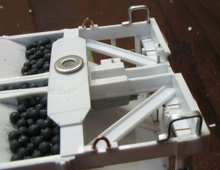
To actually install the couplers on the cars, I needed to remove material from the end sill and the center sill. The amount of material to remove is determined by the coupler's position height-wise, so it is a delicate process. Just for fun, the photo shows the collection of tools I needed to actually accomplish this carving work of the end and center sills.

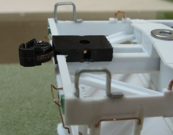
The photo shows the B end of the car. The brake equipment installed there had to be filed down as well to make the coupler's draft gear box fit. Carving away the styrene was delicate work, because you want to be careful about not cutting into other styrene parts. Needless to say, I couldn't have cut this material out early on during the construction phase, because I didn't know how high the car was going to sit, and thus determine the coupler's vertical position.

I experimented with using a single screw to attach the coupler to the body, but that didn't work out. So, I simply used superglue to glue it down to the carved out styrene. It should be strong enough for normal handling, but should something happen to the coupler itself, I should be able to snap out the coupler with some force. The couplers are my fleet's standard Walthers ProtoMax HO-scale couplers. I filed off the side mounting holes, and I dabbed a little superglue on the body parts to more securely hold them together (since I am not using screws). Finally, I trimmed off the metal uncoupler pins since I don't use those on my layout.

Although not related to the wheels and couplers, but I put it here any, and that is the installation of the airhoses. I needed to have the couplers in place before I could do these, so in model-building terms, they are related to wheels and couplers. The prototype photos show the airhose right next to the coupler, under the end sill (not through it). However, when I test-fitted that, the coupler swing was significantly reduced, which would make operating the cars on a layout more difficult. So, in the end I decided to move the airhose about 6 scale inches away from the coupler draft gear box. I am happy to say that this is the last part I am installing and I now officially declare the construction phase of these cars complete. I may install the uncoupling levers later after painting, but generally I find those interfering with operations, so I leave them off of some of my cars. We'll see.

